NURover Custom PCBs
As the Electrical team lead of NURover, Northeastern University’s University Rover Challenge (URC) team, I lead the development of 7 custom PCBs that were used in the Rover’s various subsystems. I was the Electrical lead from Fall of 2021 to Summer of 2022, and the co-lead from Fall of 2022 to mid-Spring of 2023, and throughout that time, various boards went through schematic capture, layout, inhouse fabrication, and testing and integration with the Rover.
For the sake of modularity and ease of testing, all boards were powered from two voltage sources: SMALLBATT, used for low current components such as microcontrollers and sensors; and BIGBATT, used for high current components like motors and actuators. To save space in the Rover, we stacked some of the boards and daisy chained their power and communication.

Each board included a SMALLBATT and BIGBATT in and out connector, allowing it to accept input from both power sources and send it to the next board. Each board communicated with other boards and the main computer (an Nvidia Jetson Orin module) over a custom CAN protocol. CAN was also daisy chained so that any board could be added or removed to ease debugging.
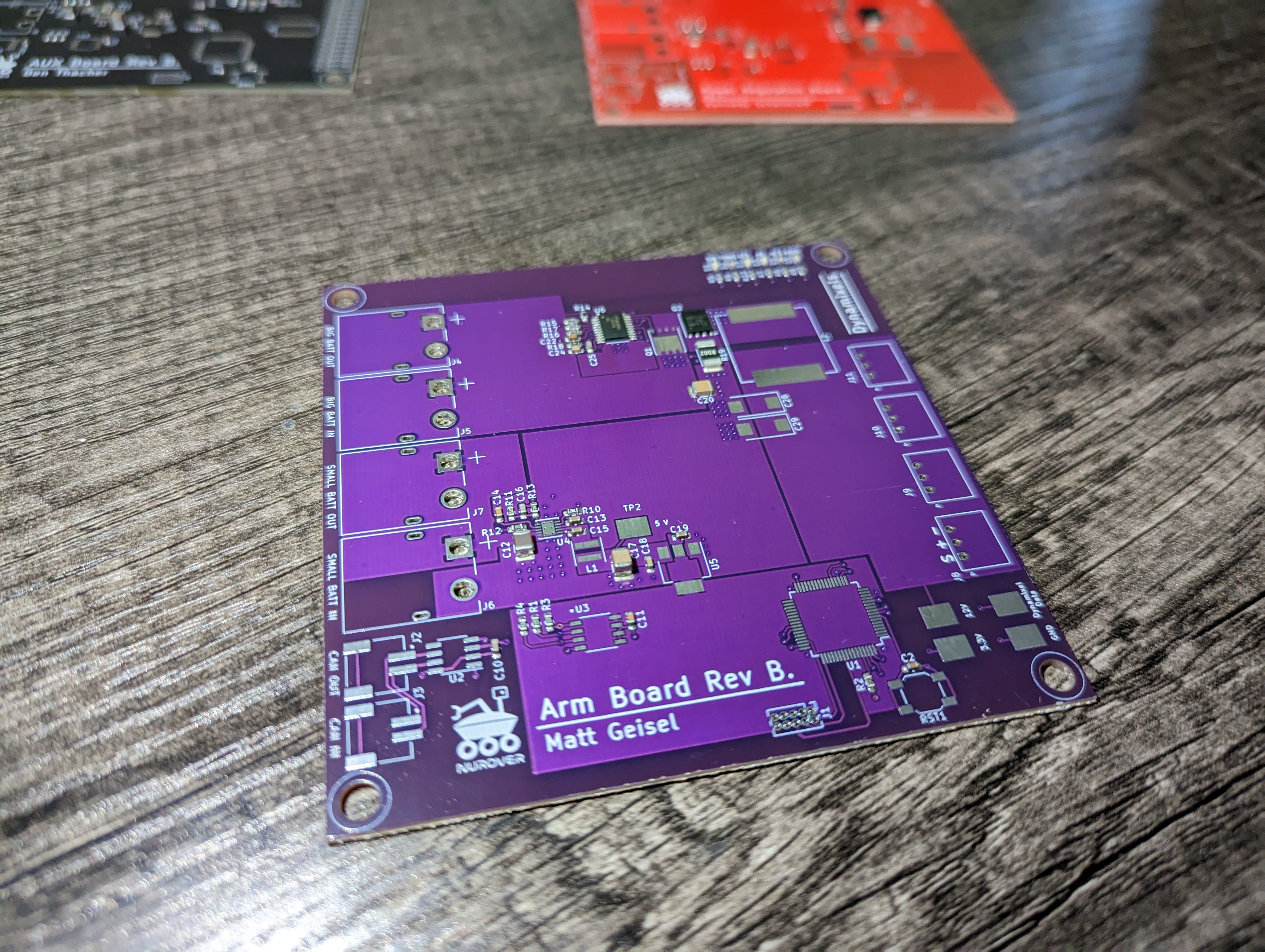
Arm Board
To help in various parts of the URC competition, the Rover was equiped with a 6 DoF manipulator. Three of the end effector joints as well as gripper actuation were controlled with Dynamixel MX64 smart servos, powered from the Arm board.
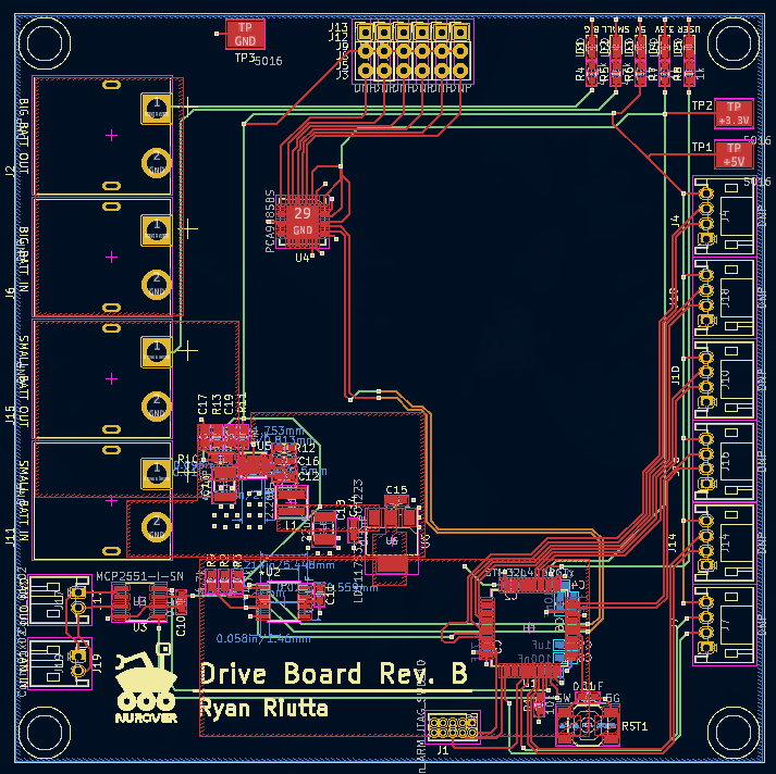
Drive Board
In 2021, we decided to attempt to make a board that integrated 6 motor controller circuits together to control the 6 drive motors on the Rover. Due to a parts shortage, we couldn’t fabricate the board and were forced to use off the shelf motor drivers. In 2022, we decided off the shelf motor drivers were much simpler, so we simplified the drive board by giving it a PWM driver chip to talk to the motor drivers.
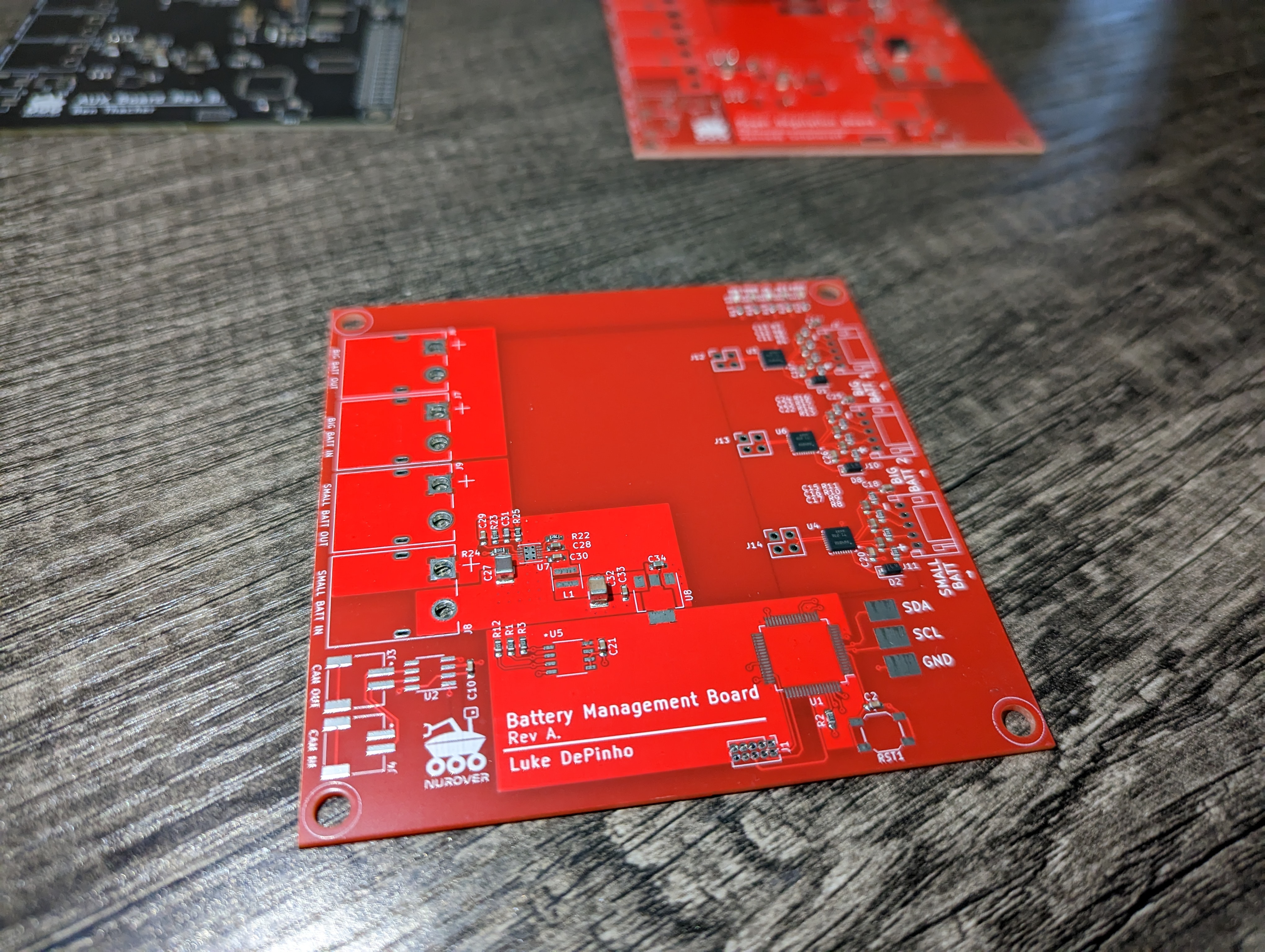
Battery Management Board
The Battery Management board was responsible for measuring the cell voltages of each of the three batteries on board (two BIGBATT, one SMALLBATT). Using TI’s BQ4050 chip, the onboard STM32 was able to quickly read all cell voltages and broadcast them to the Jetson for readout on the UI over ROS.
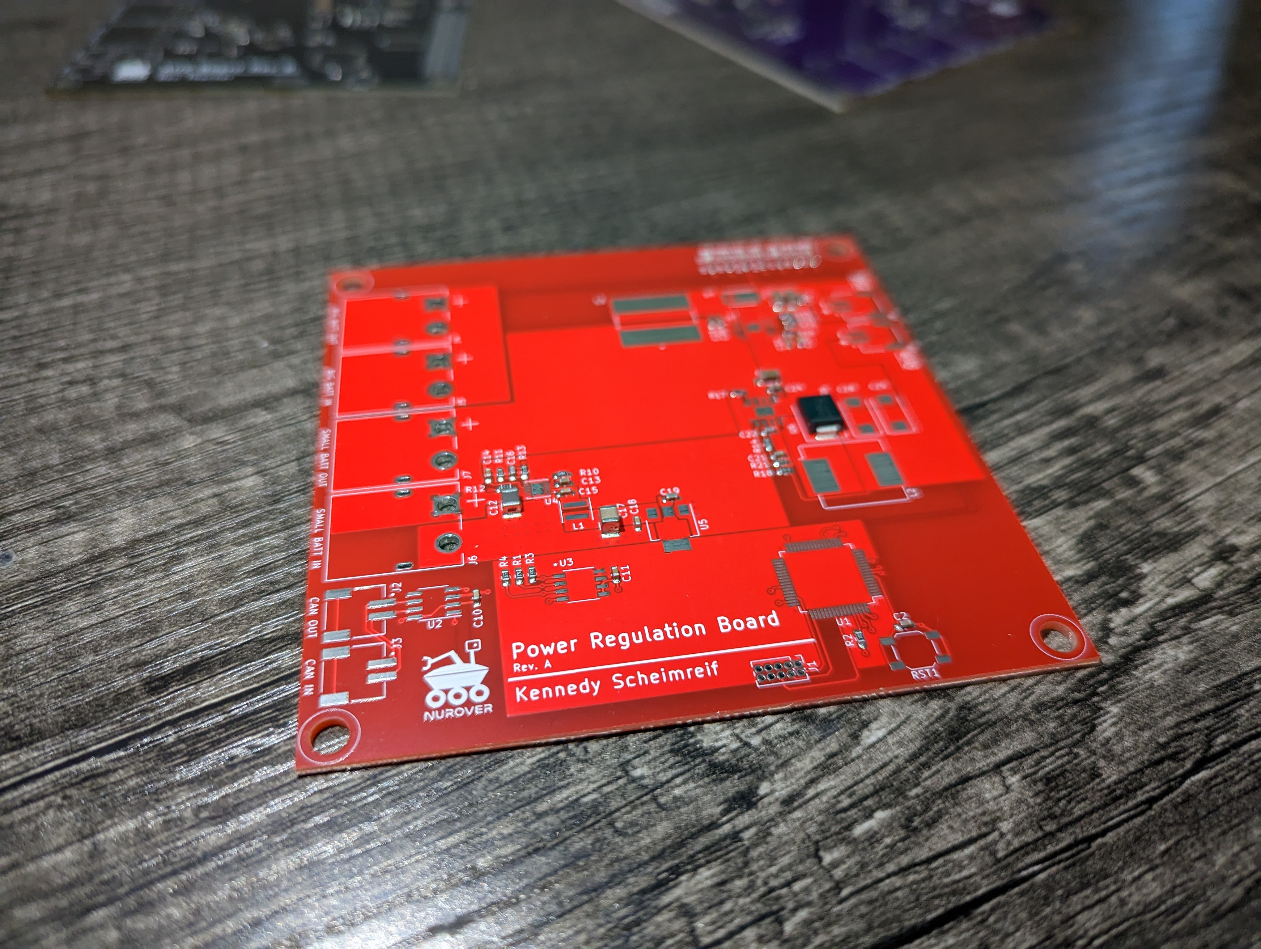
Power Regulation Board
The Power Regulation board regulated power for the Jetson and PoE injector used for the radio. It didn’t have any other responsibilities, and I think we probably could’ve integrated it into the battery management board, but I had decided the year previous that it would be better to separate the two. Realistically, having one less board is extremely helpful, as manual assembly can take a long time.
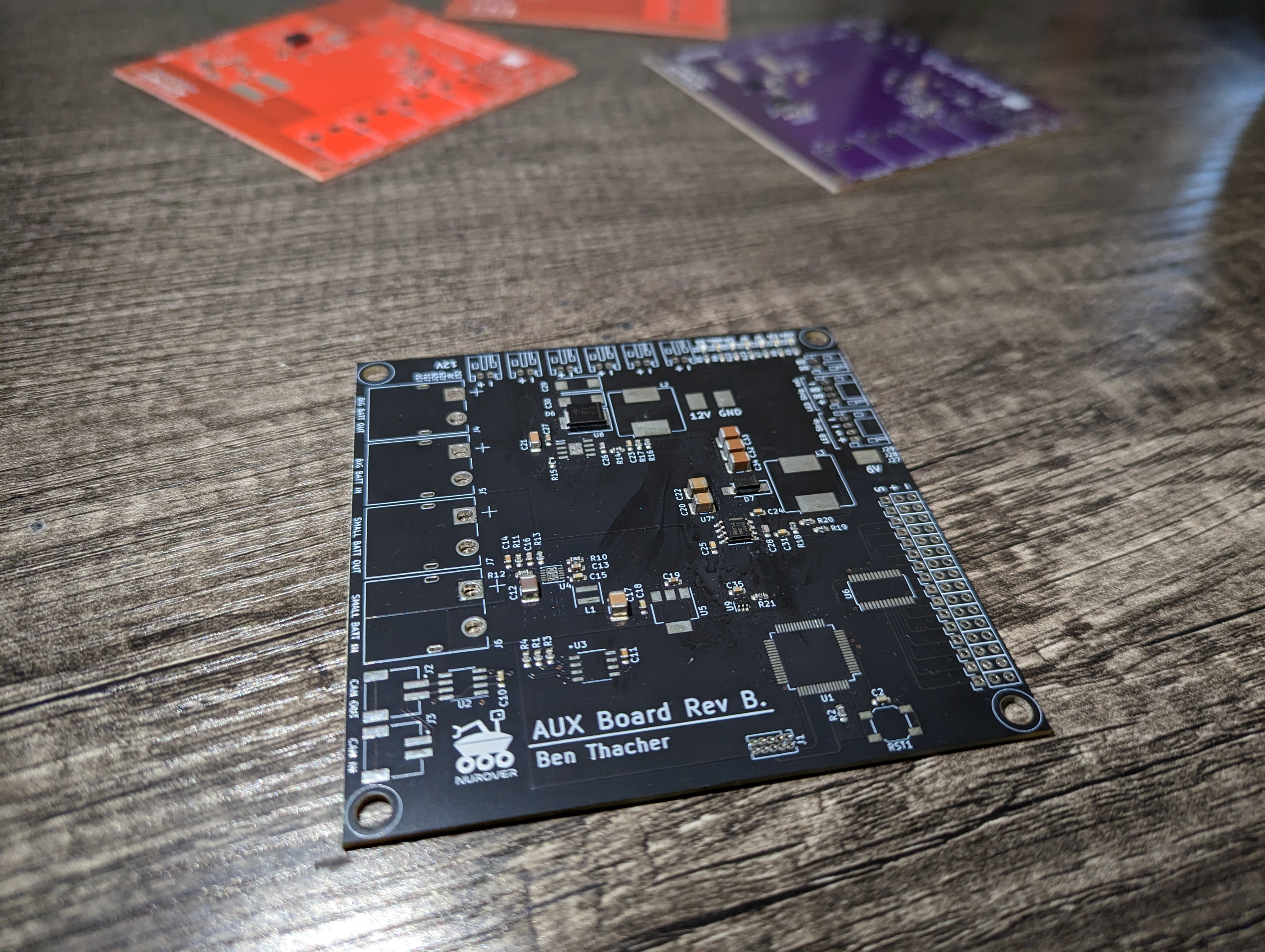
AUX Board
The AUX board contained all peripherals that didn’t have the most clear home on other boards. This included a buck regulator to power the LED strip used on the Rover, and a regulator for the pitch and yaw camera servos.